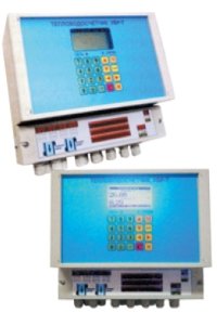
Ultrasonic Heat&Water Flow Meter UVR-T M2
 Ultrasonic Heat&Water Meter UVR-T M2 is designed to measure heat capacity and the amount of heat energy in accordance with the metering rules at industrial enterprises and public utilities:
– volume, mass, volumetric and mass flow of heating medium in the supply, return, make-up pipelines;
– operating and downtime;
– temperature and temperature difference;
– pressures.
Ultrasonic Heat&Water Meter UVR-T M2 is intended for custody transfer and process metering of heat, water and other liquids, may be included in the measurement systems, automation systems, etc.
| TECHNICAL CHARACTERISTICS: | |
| Name | Parameter |
| The type and quantity of measurement channels: | |
| – channel of flow measurement | 1 or 2 |
| – channels of pressure measurement | up to 3 |
| – channels of temperature measurement | up to 3 |
| Number of controlled heat supply systems | 1 |
| Temperature measurement range | from 0 up to 150 °С |
| Temperature difference measurement range | from 0 up to 150 °С |
| Nominal diameter of pipeline (DN): | |
| – embedded EAT | from 200 up to 4000 mm |
| – in-line section | from 25 up to 1600 mm |
| – clamp-on EAT | from 70 up to 3200 mm |
| Range of flow rate measurement | from 0,1 up to 10,0 m/s |
| Relative error of flow measurement | ±1% – for embedded EAT; ±2% – clamp-on EAT; |
| Gauge pressure in a pipeline for inserted EAT | not more than 2,5 or 6,3 МPa |
| Channels of signal input RTD: | |
| Number of Channels/Sensor Type | up to 3/RTD-Pt100, RTD-100М, RTD-50М |
| Input channels of continuous DC signals: | |
| – number of Channels | up to 3 |
| – ranges | 4÷20 мA /Rinput ≤500 Ом; 0÷5 мА /Rinput ≤2 кОм; |
| – power Supply of sensors | built-in power supply 24V |
| Absolute error of the RTD signal conversion | not more than ±0,15 °С |
| The reduced basic error of signal conversion of pressure sensors | not more than ±0,02 % |
| Indicator | graphical, LCD, size 128 x 64 pixels |
| Keyboard | membranes, 20 keys |
| Node of pulse-frequency output | pulse-frequency signal, type “dry contact” |
| Power generator | up to 15 V, current 0.05 A; not less than 0.25 W; |
| Node of the current output: | Standardized DC signal proportional to the instantaneous flow rate |
| Measurement range | 4 ÷ 20 мА or 0 ÷ 5 мА |
| Communication Channel: | Interface RS-232 or RS-485 |
| – exchange protocols | ModBus RTU |
| – speed of exchange | 4800; 9600; 19200; 38400; 57600; 115200 bit/s; |
| Power Supply: | ~220 V; 50 Hz; 5 VA / = 12 V; 3,5 W; |
| Cable from RTD to EU | РК-50; РК-75; MKESHv 1х2х0,75 or analog |
| capacitance/inductance line | not more than 15 nF/not more than 0,2 mHz |
| cable length | not more than 300m ( up to 500m on order is especially) |
| Cable from RTD to EU | PVCe 2х2х0,75 or analog; length not more than 100m |
| Operating conditions: EU | Temperature from 5 up to 50 °С; humidity up to 80%; |
| EAT | Temperature from – 20 up to 150 °С; humidity up to 100%; |
| Ingress Protection EU/EAT | IP56 / IP67 |
Features:
Ultrasonic Heat&Water Meters UVR-T M2 implement the ultrasonic time-pulse method of flow measurement. The Heat&Water Meter are configured using a built-in keyboard or RS-232/485 interface with the PC. Settings and archive data are secured to prevent unauthorized changes by restricting access to control functions via a password system and hardware-based security configuration from overwriting. The fact and the time of changes are recorded in the nonvolatile memory of the meter in the archive of interference.
The nonvolatile memory of the Heat&Water Meter stores the following:
- the quantity of thermal power;
- the quantity of heat energy;
- the volume and weight of the heating medium;
- averages of pressure and coolant temperature;
- operating time, downtime and power absence;
- event archive.
The Heat&Water Meters are furnished with the PC software intended to read archive data, form and issue reports in the form of protocols, charts and graphs.
| LIMITS OF RELATIVE ERROR OF HEAT&WATER COUNTER DURING THE MEASUREMENT OF THE QUANTITY OF HEAT DEPENDING ON THE TEMPERATURE DIFFERENCE IN THE FLOW AND REVERSE PIPELINES |
||
| Heat metering scheme | Interval of the temperature difference ΔТ °C | Relative error δт, %, not more |
| For single-line heat meters, Scheme 4,6,8 | from 5 (on) up to 10 from 10 (on) up to 20 from 20 (on) up to 145 |
+6 +5 +4 |
| For dual-line heat meters, Scheme 1…3, 7 | from 5 (on) up to 10 from 10 (on) up to 20 from 20 (on) up to 145 |
+8 +7 +5 |