Automated verification installation for gas meters APU-G-011
 PJSC “Energouchet” produces automated installations APU-G for gas meters calibration in the following modifications:
APU-G is an automated verification installation for gas meters intended for verification (calibration) and testing of turbine, rotary, ultrasonic and vortex flow meters, meters of natural gas, air, other gases and mixtures thereof, having an output pulse signal by means of comparison with reference meters. APU-G uses air as the working medium.
The installations can be used for the initial verification (calibration) of gas meters with the limits of permissible relative error of the volume flow rate measurement of ± 1,0% or more after manufacturing and after maintenance, and for periodic verification of gas meters in operation.
| Set to UVR-011A2-k-m | |||
| Modification | Name | the upper limit of measurement, m3/h, not more | the lower limit of measurement, m3/h, not more |
| APU-G-105/6,0-T | for verification of household meters | 6 | 0,016 |
| APU-G-105/10 | for verification of household meters | 10 | 0,05 |
| APU-G-105/12 | closed loop installation | 12 | 0,004 |
| APU-G-110/650M | closed loop installation | 650 | 0,1 |
| APU-G-110/1000Б | closed loop installation | 1000 | 0,16 |
| APU-G-110/1600Б | closed loop installation | 1600 | 0,25 |
| APU-G-110/2500Б | closed loop installation | 2500 | 0,5 |
| APU-G-11/650 | for verification of industrial meters | 650 | 0,1 |
| APU-G-11/2500 | for verification of industrial meters | 2500 | 0,5 |
| APU-G-11/5000 | for verification of industrial meters | 5000 | 0,4 |
| APU-G-11/6500 | for verification of industrial meters | 6500 | 1,6 |
| APU-G-11/10000 | for verification of industrial meters | 10000 | 2,0 |
Operating principle of the installation is as follows. When one of the fans is operated, airflow is created in the installation pipeline. Air flow can be controlled by varying the fan speed and using a diaphragm valve. The amount of flow rate, m3/h, is controlled by one of the reference meters. Within a given time interval (measurement cycle) the installation apparatus counts the number of pulses generated by meters under test and the reference meters. Multiplying by pulse value being individual for meters under test and the reference meter, gas volumes in working conditions are calculated. The gas volume is further recalculated to standard conditions. The error is calculated by comparing the volume of gas at standard conditions, measured by meters under test and the reference meters.
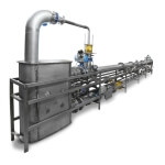
The appearance of the automated calibration installation for gas meters is shown by the example of APU-G-011/2500.
There are several options to limit the measurement cycle: by a given number of pulses received from the reference meter, when reached a predetermined volume of gas or by the operator. Installation verification is performed following the verification procedure described in para. 4.3 of the document “The automated verification installation for gas meters APU-G. Operation Manual. 636128.325 OM. Verification interval is more than 2 years.
| TECHNICAL CHARACTERISTICS | |
| Parameter | Proving rigs for Gases |
| Capacity (m3/h) | 650, 1600, 2500, 5000, 6500, 10000 |
| DN of calibrated flow meters | DN (40, 50, 80, 100, 150, 200,250, 300) |
| Type of calibrated flow meters | Ultrasonic, Turbine, Rotary |
| Relative Accuracy, % | ±0,15; ±0,3 |
| Measurement method | Comparsion with reference flow meter |
| Medium used for calibration | Air/Natural gas |
| Quantity of reference flow meters | 2,3,4,5 |
| Accuracy of temperature measurement, % | ±0,06 |
| Accuracy of pressure measurement, % | ±0,075 |