Ultrasonic Gas Meter GUVR-011

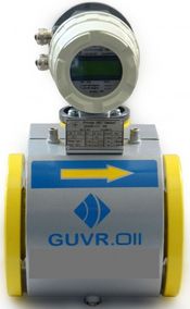
Ultrasonic gas meter GUVR-011 is designed for measuring, under operating conditions, flow velocity, volumetric flow rate and volume of natural gas and other gasses transported through the pipelines of circular cross-section in the forward or reverse direction, as well as measuring operating and down time.
Gas meters GUVR-011 provide measurement of the gas flow velocity V in the pipeline in both directions in the range from 0.1 to 25.0 m/s (under order – up to 40 m/s).
Gas Meters GUVR-011 consist of two or three components:
– one or two pairs of electroacoustic transducers (EAT) or in-line sections (IS) with embedded EAT;
– Electronics Unit (EU) with LCD or (under order) without LCD and a keyboard (airtight EU);
– Power Supply and Communication Unit (PCU) with control and indication means located at distance not more than 300 m from the EU.
The GUVR-011 meter can be supplied with the in-line section with one (two) pairs of EAT installed in the in-line section (as built) or one (two) pairs of EAT mounted on the measurement section of the pipeline on-site.
Minimal gauge pressure of the gas which allows for GUVR-011 gas meter normal operation constitutes 0 MPa. The meters are used both for custody transfer and process applications to measure natural and other gases (associated gas, nitrogen, oxygen, compressed air etc.).
| FLOW RATE OF FLOW METERS WITH IN-LINE SECTIONS | ||||||
| DN, mm | Dimension
type |
Volume flow rate, m3/h | Maximal, Qmax |
|||
| Threshold, Qthr |
Minimal, Qmin |
Transition, Qt | ||||
| 1,00% | 0,50% | |||||
| 50 | G100 | 0,7 | 1 | 8 | 11 | 250 |
| 80 | G250 | 1,9 | 2,7 | 20 | 27 | 400 |
| 100 | G400 | 3 | 4 | 33 | 44 | 650 |
| 100 | G650 | 3 | 4 | 33 | 50 | 1000 |
| 150 | G1000 | 7 | 10 | 80 | 110 | 1600 |
| 150 | G1600 | 7 | 10 | 80 | 125 | 2500 |
| 200 | G1600 | 12 | 17 | 125 | 170 | 2500 |
| 200 | G2500 | 12 | 17 | 125 | 200 | 4000 |
| 250 | G2500 | 19 | 26 | 200 | 270 | 4000 |
| 250 | G4000 | 19 | 26 | 200 | 325 | 6500 |
| 300 | G4000 | 28 | 40 | 325 | 440 | 6500 |
| 300 | G6500 | 28 | 40 | 325 | 500 | 10000 |
| 400 | G6500 | 47 | 67 | 500 | 670 | 10000 |
| 400 | G10000 | 47 | 67 | 500 | 800 | 16000 |
The diameter of the pipeline ranges from 50 to 4000 mm. The basic relative error of measurement ±0.3% to ±2%. The meters are used to measure gas, including custody transfer applications at gas distribution points, industrial facilities, power facilities and public utilities. The meters can be used to measure the flow rate of pure gases, contaminated gases, gathering lines, in underground gas storage facilities, gas torches etc.
| FLOW RATE OF FLOW METERS WITH EMBEDDED SENSORS | |||||
| DN, mm | Volume flow rate, m3/h | ||||
| Dimension
type |
Threshold, Qthr |
Minimal, Qmin | Transition, Qt | Maximal, Qmax | |
| 200 | G1600 | 12 | 17 | 125 | 2500 |
| 250 | G2500 | 19 | 26 | 200 | 4000 |
| 300 | G4000 | 28 | 40 | 325 | 6500 |
| 400 | G4000 | 47 | 67 | 500 | 10000 |
| 500 | G10000 | 71 | 100 | 800 | 16000 |
| 600 | G16000 | 111 | 160 | 1250 | 25000 |
| 700 | G16000 | 111 | 160 | 1250 | 25000 |
| 800 | G25000 | 117 | 250 | 2000 | 40000 |
| 1000 | G40000 | 228 | 400 | 3250 | 65000 |
| 1200 | G65000 | 470 | 670 | 5000 | 10000 |
| 1600 | G100000 | 700 | 1000 | 8000 | 160000 |
| 2000 | G160000 | 1110 | 1600 | 12500 | 250000 |
| 2500 | G250000 | 1900 | 2700 | 20000 | 400000 |
| 3000 | G400000 | 2800 | 4000 | 32500 | 650000 |
| 4000 | G650000 | 4700 | 6700 | 50000 | 1000000 |
| LIMITS OF PERMISSIBLE MAIN RELATIVE ERROR OF FLOW METERS | ||||
| Flow rate value | Limits of permissible main relative error, % | |||
| In-line section | Embedded sensors | |||
| Two pair | One pair | Two pair | One pair | |
| from Qmin up to Qt | ± 1*(2) | ± 3 | ± 4 | ±5 |
| from Qt up to Qmin | ± 0,5*(1) | ± 1,5 | ± 2 | ± 3 |
| * – for variation GUVR-011 А2.2/ВС/…/0,5% | ||||


